SQUARE 320 PROJECT
1199 F Street NW, Wash, DC 20004
Michael Webb Construction Management Option
Building Statistics
| Home | |
| Michael Webb | |
| Building Statistics | |
| Thesis Abstract | |
| Technical Assignments | |
| Thesis Research | |
| Thesis Proposal | |
| Presentation | |
| Final Report | |
| Reflection | |
| Senior Thesis eStudio | |
|
|
|
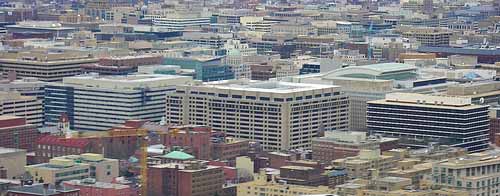
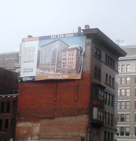
Pre-Construction Site |

![]()
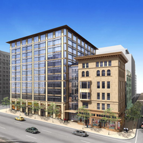 |
| Rendering from the corner of 1199 F Street |
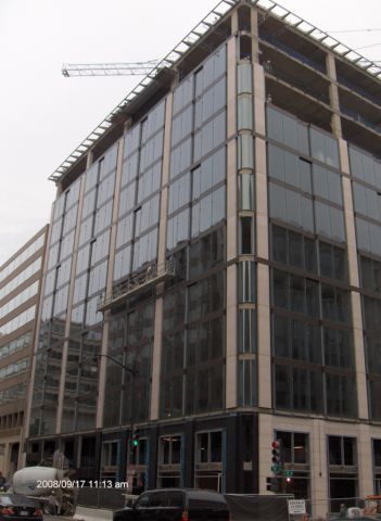 |
The Office Tower |
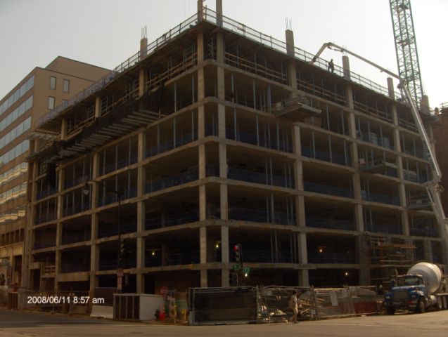 |
The Office Tower |
Construction Manager: James G. Davis Construction Corporation Architect: Pei Cobb Freed & Partners Architects LLP w/ Shalom Baranes Associates
The Square 320 Project is favorably located at 1199 F Street NW, the corner of 11th and F, in the resurgent East End submarket of Washington DC. Square 320 incorporates the renovation of four historic buildings with the construction of a new 12-story concrete building to create Class A office space. This exciting renovation project sits on top of 5-stories of below-grade parking totaling 74,300-SF and offering 167 parking spaces. Above grade, the new 12-story concrete structure will create 302,000-SF of rentable office space. Construction began in October of 2007 and is expected to last for 41 months through February of 2011. This project is a joint venture between owners Douglas Development Corporation and CarrAmerica, now part of Equity Office, and is expected to reach an overall project cost of $110 million. At this stage there are no significant tenants committed but Square 320 is expected to attract larger law firms from the central business district.
Architecture Some of the major National codes include: 2003 Int’l Building Code, 2003 Int’l Mechanical Code, 2003 Int’l Plumbing Code, 2003 Int’l Electric Code, and ADA Accessibility. The District of Columbia has very strict zoning restrictions to both protect the historic nature of the city while stimulating economic growth. Square 320 is located in the downtown core, C-4, which comprises the retail and office centers of the District of Columbia. This designated district allows office, retail, housing and mixed uses to a maximum lot occupancy of 100% and a maximum height of 110 feet and 130 on 110-foot adjoining streets. Additionally, this subsection of DC is called the Downtown Development District (DD) permitting incentives and requirements for Downtown sub-areas to a maximum floor area ratio (FAR) of 6.0 to 10.0, and a maximum height of one hundred-thirty (130) feet.
Building Statistics Part 2 Excavation Support Lighting & Electrical System Mechanical System Structural Structural Steel Frame Special Systems Masonry
|
|